Creation and evaluation of a 3D terrain model from drone data by means of PointCab

TitleVolumenberechnung mittels Drohnenvermessung
In diesem Anwenderbericht erklären wir Ihnen übersichtlich die Arbeitsschritte von der Flugplanung mit der UAV (Drohne), den Arbeiten vor Ort, der Berechnung der Punktwolke im Nachgang und die Auswertung der Geländedaten in der Software PointCab. Ziel des Projektes war es einen Steinbruch mittels Drohne zu vermessen und die erforderlichen Bergbautechnogologischen Auswertungen vorzunehmen. Hierbei ging es vorrangig um das Grubenbild, die Grubengeometrie und um Volumenberechnungen.
In this user report, we clearly explain the work steps from flight planning with the UAV (drone), work on site, subsequent calculation of the point cloud, and the evaluation of the terrain data in the PointCab software. The aim of the project was to survey a quarry by means of a drone and to carry out the required evaluations with regard to mining technology. This mainly concerned the pit pattern, the pit geometry, and volume calculations.
Planning phase (flight preparation)
In preparation for the aerial inspection by the UAV (drone), passing points were sprayed on the ground with signal paint. The passing points were then localized with a GPS receiver and the positions saved.
.jpg)
To ensure a safe and smooth flight, the terrain was inspected and its topological conditions examined in consultation with those working on the terrain. These data were used to create a flight plan. In this flight plan, metadata of the camera and the desired flight altitude were entered in the software to obtain the greatest possible accuracy later. The flight plan was then transferred onto the UAV.
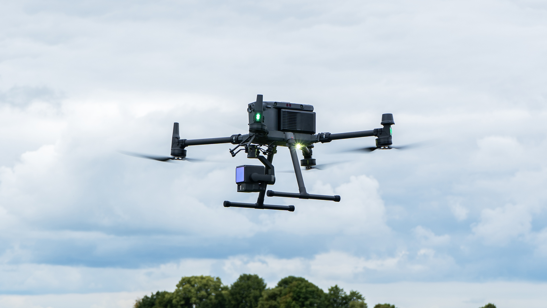
Flight phase
The UAV flew across the coordinates autonomously and triggered the camera at the right point in time to create the necessary images. A pilot was not necessary; he merely monitored the process and checked the smooth sequence of the flight. As soon as the UAV had concluded its flight, the pilot landed the drone. Subsequently, a new flight plan was created, taking its starting point from the previous plan.
Creation of the point cloud in the Agisoft Photoplan program
In the first step, the images were aligned in relation to one another, thus creating a rough point cloud. The GPS points measured in the preparations were linked to the colored passing points on the ground. The roughly calculated point cloud was then aligned exactly to the GPS passing points, creating a high-resolution point cloud with exact coordinates in the national grid. In order to be able to work better with the data as the project progressed, the surface was meshed – i.e. a calculation was used to place a "mesh grid" over the point cloud. Thereafter, there is the possibility to output the point cloud in various file formats.
Evaluation of the data in PointCab
The data were imported into PointCab and processed. PointCab used the point cloud data of the drone in the common *.las format. In this project, we referenced the point cloud from Agisoft onto the passing points once again. In our experience, this enhances the accuracy. Next, PointCab was used to generate a surface model. We used this model later in Autodesk. In addition, it was a simple task to use PointCab to obtain distances, lines, surfaces, sections, volumes, 3D elevation points, and other information. The great advantage of PointCab is that the software is very easy to operate and can be used by a great many users without extensive prior knowledge.
In the following tutorial, the drone specialists at anvitech will show you how simple it is to operate the software.
TitleFlugphase
Die UAV flog die Koordinaten selbstständig ab und löste zum richtigen Zeitpunkt die Kamera aus und erstellte die nötigen Bilder. Ein Pilot war nicht notwendig, er überwachte lediglich den Prozess und kontrollierte den reibungslosen Ablauf des Fluges. Sobald die UAV Ihren Flug abgeschlossen hatte, landete der Pilot die Drohne. Anschließend wurde ein neuer Flugplan erstellt, der an den vorherigen anschloss.
TitleErstellung der Punktwolke im Programm Agisoft Photoplan
Im Ersten Schritt wurden die Bilder zueinander ausgerichtet. Daraus entstand eine grobe Punktwolke. Die im Vorlauf gemessenen GPS-Punkte wurden mit den farbigen Passpunkten auf dem Boden verknüpft. Danach wurde die grob berechnete Punktwolke nach den GPS-Passpunkten ausgerichtet und es entstand eine hochauflösende Punktwolke mit genauen Koordinaten im Landesnetz. Um im späteren Verlauf besser mit den Daten arbeiten zu können, wurde die Oberfläche vermesht – Durch Berechnung wurde ein „Mesh-Gitter“ über die Punktwolke gelegt. Danach gibt es die Möglichkeit die Punktwolke in verschiedene Dateiformate auszugeben.
TitleAuswertung der Daten in PointCab
Die Daten wurden in PointCab eingespielt und verarbeitet. PointCab verwendete die Punktwolkendaten der Drohne im gängigen *.las Format. Bei diesem Projekt haben wir die Punktwolke aus Agisoft nochmal auf die Passpunkte referenziert. Unserer Erfahrung nach kann dadurch eine Steigerung der Genauigkeit erzielt werden. Mittels PointCab wurde im weiteren Verlauf ein Oberflächenmodell erzeugt. Dieses Modell verwendeten wir später in Autodesk. Zusätzlich war es möglich, mit PointCab einfach Strecken, Linien, Flächen, Schnitte, Volumen, 3D-Höhenpunkte und weitere Informationen zu ermitteln. Der große Vorteil von Pointcab ist, dass die sehr einfach zu bedienende Software von vielen Nutzern, ohne große Vorkenntnisse verwendet werden kann.