How To: Surveying of sewer manhole with a laser scanner & a manhole tripod

TitleVermessung von Schächten
Die Vermessung und Inspektion von Abwasserschächten ist ein essenzieller Bestandteil der Instandhaltung und Dokumentation von Kanalsystemen. Traditionell erfordert diese Aufgabe den Einstieg geschulter Fachkräfte in die Schächte, was mit erheblichem Aufwand und Sicherheitsrisiken verbunden ist. Um diesen Prozess zu optimieren und die Arbeitssicherheit zu erhöhen, kommen zunehmend moderne Vermessungstechnologien wie Laserscanner zum Einsatz. Durch den Einsatz eines Schachtstativs kann der Scanner in den Schacht herabgelassen werden, sodass eine detaillierte Erfassung der Schachtgeometrie erfolgt – ohne dass ein direkter Personeneinstieg erforderlich ist.
Survey environment
The survey environment are manholes that serve as access for maintenance and cleaning of the sewer system. The manholes usually have a diameter between 600mm and 800mm and are constructed with iron or brick steps to facilitate access and egress for people.
Problems related to the surveying of manholes
In order to document the condition of the shafts, an inspection of the shaft system is required. This can be done by specially trained operators by means of visual inspection. However, this requires a person to enter the shaft. The person has to be protected by additional personnel and safety equipment (CO2 measuring device, tripod with rappelling technique, climbing harness, special work clothes, etc.) in order to avoid personal injury.
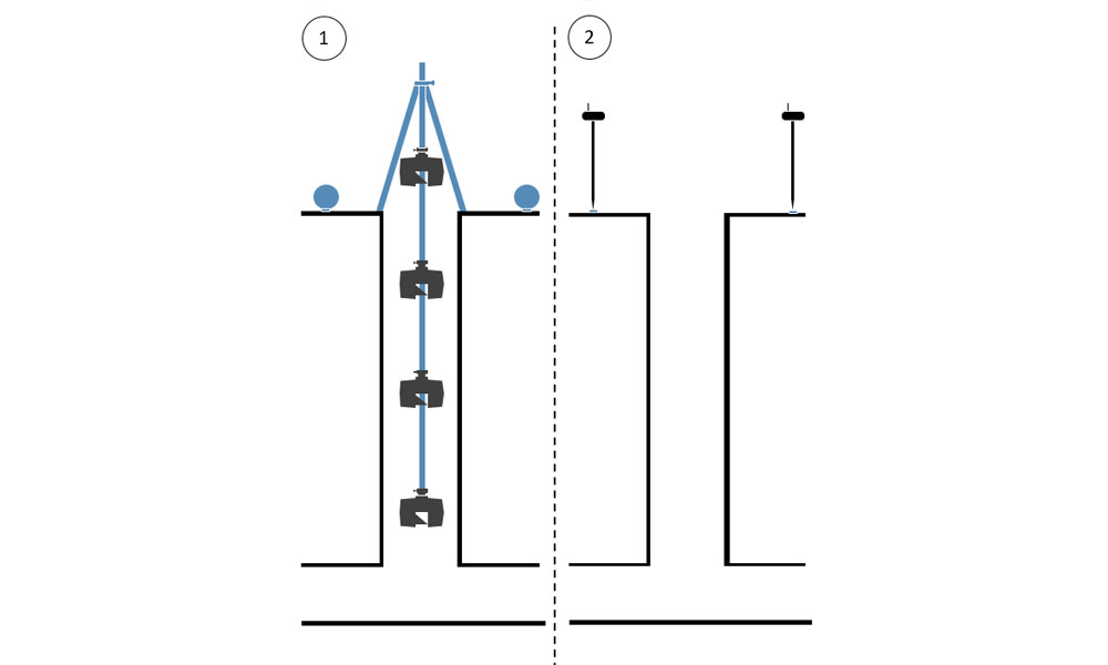
One approach to avoid personal entry into the shafts is to scan with a laser scanner. By using a manhole tripod (2-way tripod), the laser scanner can be lowered into the shaft. Reference spheres (spherical targets) positioned close to the shaft are also detected by the laser scanner and subsequently surveyed tachymetrically or by means of GNSS survey to ensure georeferencing.
Equipment for manhole surveying
The following equipment was used for the survey of the shafts:
- Laser scanner from the manufacturer FARO (other equipment is also possible).
- 2-way telescope tripod / manhole tripod from Laserscanning Europe (The manhole tripod is available with safety adapters for various scanner models).
- Overhead adapter for FARO laser scanner from Laserscanning Europe
- At least 3 reference spheres (type FLEXI) from Laserscanning Europe
- GNSS receiver (or total station equipment) for georeferencing
- If necessary, barrier type or similar to secure the shaft opening
Procedure of the survey
- Opening of the shaft and securing of the site if necessary.
- Setting up the manhole tripod above the center of the shaft. The tripod should be approximately horizontal so that the laser scanner can be lowered into the center of the shaft.
- Mounting the scanner to the manhole tripod using the overhead adapter.
- Turning on the scanner and activating the wireless remote connection.
Creating a project and setting the corresponding parameters in the scanner. - To start with the lowest scan in the shaft, the scanner is lowered section by section. This is done either with the hand crank or in a faster way with a cordless screwdriver. Gradually, the rod segments of the manhole tripod are added to achieve the necessary depth in the shaft. Then the scanning process is started with the help of a smartphone via the remote connection. Once the scan has been completed, a preview can be viewed.
- Further scans now follow along the entire height of the shaft: approximately every 1m – 2m a scan. Depending on the further processing of the scan data, however, this distance can be flexibly selected.
- The topmost scan is performed about 0.5m above the surface. In this scan, the reference spheres (at least 3 spheres) are also placed well distributed around the shaft opening so that they are visible to the laser scanner. After the last scan has been performed, the scanner can be switched off and disassembled. The manhole tripod can be removed and the shaft closed again.
- For georeferencing, the sphere positions must now be measured, e.g. with a GNSS receiver. Alternatively, this can also be done by total station, provided that known connection points of sufficient quality can be found in the surrounding area.
The survey is now complete. An experienced operator needs max. 1 hour for this.
Workflow of the analysis
- Backing up the scan data and the GNSS points
- Merging of the individual scans with each other. This is done automatically in the FARO SCENE software using Cloud-2-Cloud registration. The result after successful merging is an overall 3D point cloud, i.e. a digital image of the surveyed shaft.
- Georeferencing is also performed in the FARO SCENE software. First, the centers of the reference spheres placed in the last (top) scan are determined. This is done automatically using the search algorithm in the FARO SCENE software. When importing the GNSS points, make sure that the height offset between the sphere center and the ground point determined with the GNSS receiver has been taken into account beforehand. Then a 3D transformation is performed, aligning the scan data to those with GNSS reference points.
- The processing of the scan data including georeferencing is now complete. An experienced operator needs max. ½ hour for this process.
- The overall point cloud can now be exported and further processed e.g. in PointCab software or a CAD software.
Do you have questions about how to best execute your projects? Simply send us a mail to info@laserscanning-europe.com or call us at +49 (0)391 6269960.
> Laser scanner accessories for your projects
TitleEquipment für die Schachtvermessung
Das folgende Equipment wurde für die Vermessung der Schächte eingesetzt:
- Laserscanner vom Hersteller FARO (andere Geräte sind auch möglich)
- 2-Way-Kurbelstativ / Schachtstativ von Laserscanning Europe (Das Schachtstativ ist mit Sicherheitsadapter für verschiedene Scanner-Modelle erhältlich.)
- Überkopfadapter für FARO Laserscanner von Laserscanning Europe
- Mindestens 3 Referenzkugeln (Typ FLEXI) von Laserscanning Europe
- GNSS-Empfänger (oder Tachymeterausrüstung) für die Georeferenzierung
- Ggf. Absperrmaterial zur Sicherung der Schachtöffnung
TitleAblauf der Vermessung
- Öffnung des Schachtes und ggf. Absicherung der Örtlichkeit.
- Aufstellen des Schachtstativs über der Schachtmitte. Das Stativ sollte nur ungefähr horizontiert werden, damit der Laserscanner mittig in den Schacht herabgelassen werden kann.
- Montage des Scanners mit Hilfe des Überkopfadapters am Schachtstativ.
- Einschalten des Scanners und Aktivierung der Wireless-Remote-Verbindung.
Anlegen eines Projekts und Einstellen der entsprechenden Parameter am Scanner. - Um mit dem untersten Scan im Schacht zu beginnen, wird der Scanner Stück für Stück heruntergelassen. Dies erfolgt entweder mit der Handkurbel oder auf schnellerem Wege mit einem Akkuschrauber. Nach und nach werden die Stangensegmente des Schachtstativs nachgesteckt, um so die notwendige Tiefe im Schacht zu erreichen. Anschließend wird der Scanvorgang mit Hilfe eines Smartphones über die Remote-Verbindung gestartet. Nach dem der Scan fertiggestellt wurde, kann eine Vorschau betrachtet werden.
- Weitere Scans folgen nun entlang der gesamten Höhe des Schachtes: etwa alle 1 – 2 m ein Scan. Je nach Weiterverarbeitung der Scandaten ist dieser Abstand aber flexibel wählbar.
- Der oberste Scan wird etwa 0,5 m oberhalb der Oberfläche durchgeführt. In diesem Scan werden auch die Referenzkugeln (mindestens 3 Stück) gut verteilt um die Schachtöffnung herum platziert, sodass sie für den Laserscanner sichtbar sind. Nach erfolgtem letztem Scan kann der Scanner ausgeschaltet und demontiert werden. Das Schachtstativ kann abgebaut und der Schacht wieder verschlossen werden.
- Für eine Georeferenzierung müssen nun die Kugelpositionen z. B. mit einem GNSS-Empfänger eingemessen werden. Alternativ kann dies auch tachymetrisch erfolgen, vorausgesetzt man findet bekannte Anschlusspunkte ausreichender Güte in der Nähe.
Das Aufmaß ist nun abgeschlossen. Ein routinierter Mitarbeiter benötigt dafür max. 1 Stunde.
TitleAblauf der Auswertung
- Sicherung der Scandaten und der GNSS-Punkte
- Verknüpfung der einzelnen Scans miteinander. Dies erfolgt automatisiert in der Software FARO SCENE mit Hilfe der Cloud-2-Cloud-Registrierung. Das Ergebnis nach erfolgreicher Verknüpfung ist eine 3D-Gesamtpunktwolke, also ein digitales Abbild des vermessenen Schachtes.
- Die Georeferenzierung erfolgt ebenfalls in der Software FARO SCENE. Zunächst werden die Kugelmittelpunkte der im letzten (obersten) Scan platzierten Referenzkugeln ermittelt. Dies gelingt automatisch mit Hilfe des Suchalgorithmus in der FARO SCENE Software. Beim Import der GNSS-Punkte ist darauf zu achten, dass vorher der Höhen-Offset zwischen dem Kugelmittelpunkt und dem mit dem GNSS-Empfänger ermittelten Bodenpunkt berücksichtigt wurde. Dann erfolgt eine 3D-Transformation, die die Scandaten an denen mit GNSS-Referenzpunkten ausrichtet.
- Die Aufbereitung der Scandaten inkl. Georeferenzierung ist nun abgeschlossen. Ein routinierter Mitarbeiter benötigt für diesen Prozess max. ½ Stunde.
- Die Gesamtpunktwolke kann nun exportiert werden und z. B. in der Software PointCab oder einer CAD-Software weiterverarbeitet werden.