Last year, Laserscanning Europe GmbH was given the opportunity to be part of a team in the capturing and modelling of bridge constructions. Together with its partners, Verkehrs- & Ingenieurbau Consult GmbH (VIC GmbH) and Ingenieur-Vermessung Dresden GmbH (IHH), eight bridge constructions of a motorway interchange were processed on behalf of DEGES.
 bridge constructions of a motorway interchange
The challenge - Which software is best suited for this project?
The job was to model the eight bridge constructions BIM ready and three-dimensionally. The focus was on the bridge construction itself, including the abutments, caps, piers, construction joints, crossing track systems, steel construction and piping. The modelling of the adjacent terrain played a rather subordinate role for the CAD team, as the terrain mapping was already available in the form of a site map and elevation plan and all the required information on the terrain could be taken from the plan.
The team questioned in advance which software would best meet all the requirements of the service specifications. Among others, the software solutions AutoCAD, MicroStation, Revit and ArchiCAD were considered. The team quickly agreed to model in Autodesk Revit.
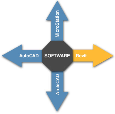
The following aspects were decisive for the use of Autodesk Revit:
- All requirements of the specification can be met.
- Revit is a software often used in civil engineering.
- Revit offers good modification management.
- Revit is a good software for analysis and collision detection.
- Revit offers the perfect basis for handing on to technical planners and engineers.
- The CAD team has many years of experience with the software.
Modelling - How did the team work?
The basis
Based on the site and elevation plan of the VIC GmbH in the coordinate system ETRS89 32.Streifen and the registered scan data of the office IHH, the CAD experts started with the modelling of the objects.
The transferred point clouds were exported into the data format RCP and referenced into the Revit project file via the definition of the reference point. PointCab software (www.pointcab-software.com) was used for visualisation, accuracy control, use of panorama images and generation of auxiliary sections and layouts.
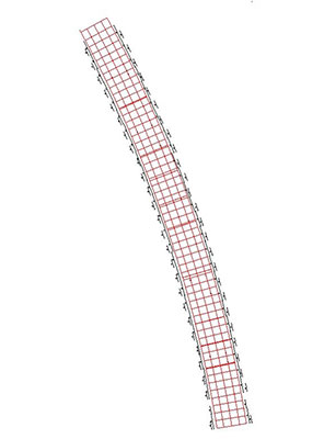
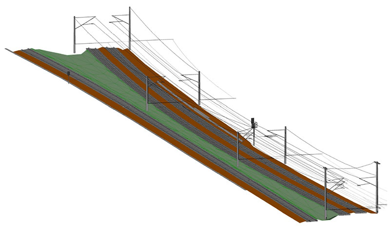
 Point cloud of the track systems
The modelling steps
For the modelling of the first bridge, the team generated its own modelling workflow, which was also used for all other bridges. This process was structured as follows:
-
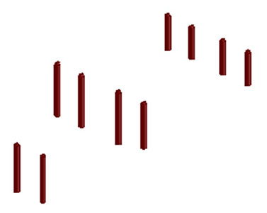
Placement of piers and columns
-
Modelling of the bridge superstructure
- Definition of the edge axes of the bridge structure
-
Splitting of the edge axes into profile-like straight sections and placement of auxiliary lines and sections
-
Modelling of the bridge structure using the previously generated auxiliary construction
-
Placement of stairs, abutments, walls, railings, etc.
-
Modelling of steel construction, tracks, overhead lines, construction joints, piping, etc. analogous to the bridge structure
-
Combination with the meshed terrain from the site map
As expected, some difficulties arose in the course of modeling, which the team was able to solve with a special approach thanks to many years of experience.
The modelling of the highly curved and inclined bridge structures as well as the modelling of the inclined tracks turned out to be particularly complicated. For this purpose, the modellers dismantled the bridge and tracks into boundary axes and auxiliary structures and carried out the modelling via these axes, as can already be seen from the modelling process. This resulted in very complex project families.
The modelling of overhead lines, tracks and joints was difficult because these "filigree" objects are not as precisely mapped in the point cloud at normal scanning density.
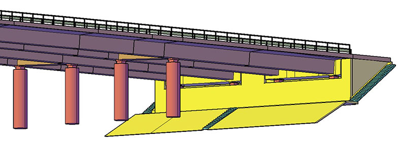
In addition, the steel construction was complex, as each component had to be modelled separately.
 Modelling of steel construction
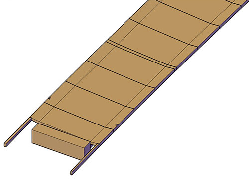
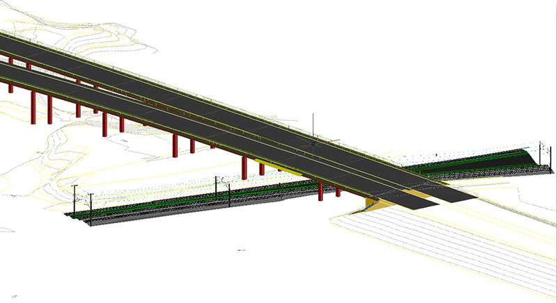
 Modelled bridges with point cloud
Conclusion
The decision to use Autodesk Revit software also enabled the CAD team to provide additional analysis. At the push of a button, for example, the following information was quickly determined:
- Number/volume of piers and columns
- Linear metres of lines and railings
- Number of sleepers and masts
- Volume of the bridge structure
After about half a year, the project was completed and the data was transferred in the formats RVT, DWG and 3D PDF.
The project was an enrichment for the CAD team of Laserscanning Europe and a complete success thanks to the excellent cooperation with VIC GmbH and IHH GmbH.

Do you also need a 3D model? Simply contact us by phone at +49 (0)391 6269960 or by e-mail at info@laserscanning-europe.com. We are happy to support you with the modelling service based on scan data. Simply contact us!


